IPSec VPN — Overlapping Subnets (X-Pool)
Navigation: Scenarios → IPSec Overlapping Subnets
Build a site-to-site IPSec VPN when local and remote subnets are identical (for example both sites use 192.168.1.0/24). Enable Install Policy on the tunnel, set Phase 2 local and remote networks to the same CIDR, align the inline firewall rule with Phase 2 selectors, apply X-Pool SNAT to translate local sources, and set Destination Interface to the VPN tunnel interface name (tun_ipsec_*).
Critical: Phase 2 Local Networks and Remote Networks must use the same subnet as the real networks — the firewall breaks the overlap with X-Pool NAT, not by changing Phase 2 to the pool range.
Network design
Both Site A and Site B use 192.168.1.0/24. IPSec Phase 2 negotiates 192.168.1.0/24 ↔ 192.168.1.0/24. Before packets enter the tunnel, the local firewall rewrites the source to 10.255.1.0/24 (X-Pool) so the remote site can route replies.
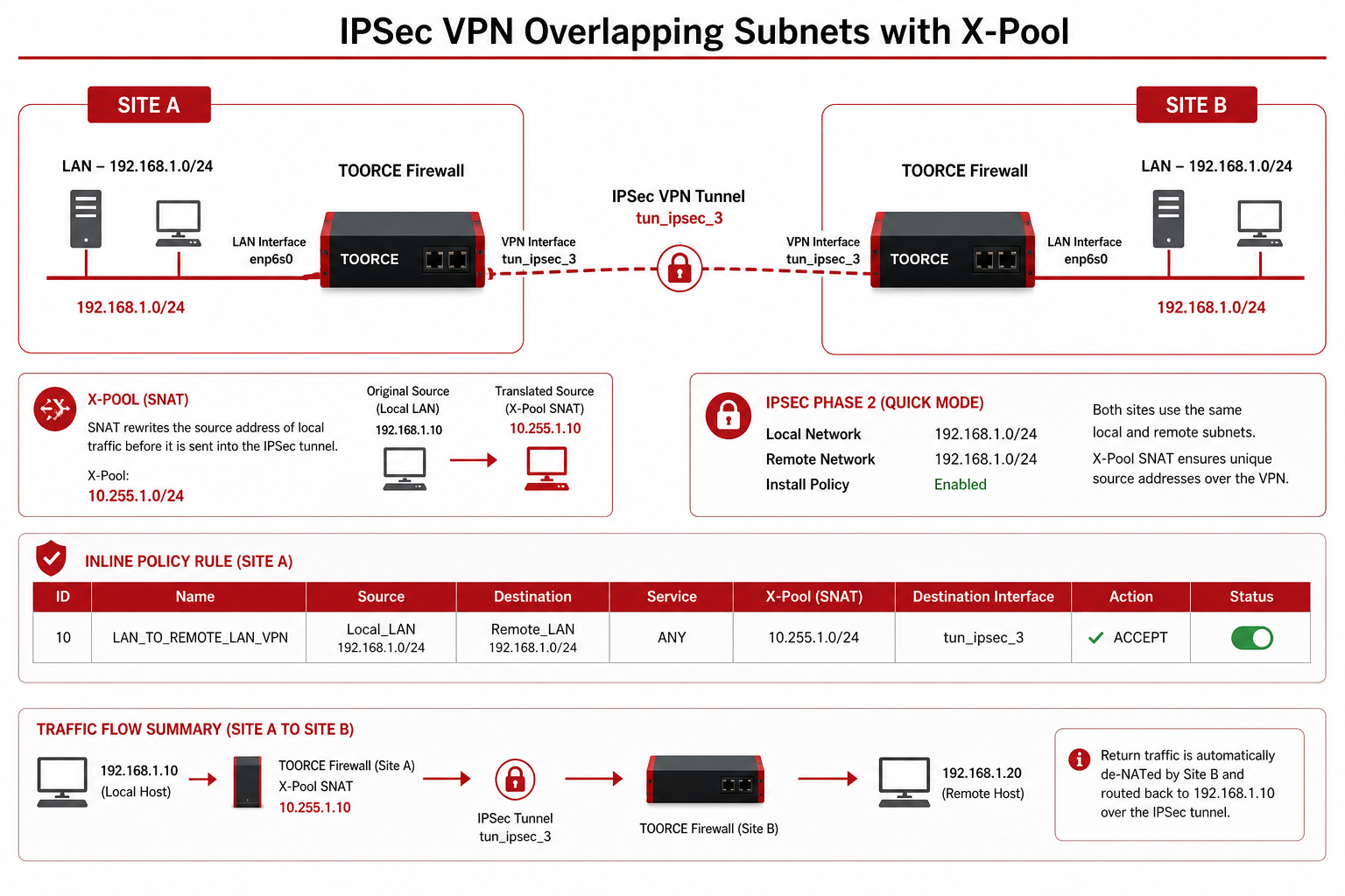
Figure 1 — Identical Phase 2 subnets, X-Pool SNAT, VPN interface on inline rule
Addressing summary
| Role | Object / range | CIDR | Used in |
|---|---|---|---|
| Real local LAN | Local_LAN |
192.168.1.0/24 |
Phase 2 Local + rule Source |
| Real remote LAN | Remote_LAN |
192.168.1.0/24 |
Phase 2 Remote + rule Destination |
| X-Pool SNAT | XPool_SNAT / pool-X |
10.255.1.0/24 |
SNAT Policy on outbound rule |
| VPN interface | tun_ipsec_3 (ToorceVPN) |
— | Rule Destination Interface |
End-to-end flow
1. PC 192.168.1.10 → remote 192.168.1.50
2. Inline rule matches: Source Local_LAN, Dest Remote_LAN, Dest IF = tun_ipsec_3
3. SNAT Policy pool-X rewrites source → 10.255.1.10
4. IPSec Phase 2 encrypts (selectors: 192.168.1.0/24 ↔ 192.168.1.0/24)
5. Remote receives from 10.255.1.10, replies to 10.255.1.10
6. Return de-NAT → 192.168.1.10
Prerequisites
- WAN connectivity to remote peer public IP
- Matching PSK or certificates on both peers
- Agreed X-Pool range (
10.255.1.0/24) — must not exist at either site - Address objects created first
Step 1 — Create address objects
Go to Aliases & Objects → Address:
| Object name | Type | Value | Purpose |
|---|---|---|---|
Local_LAN |
Network | 192.168.1.0/24 |
Real local subnet (= Phase 2 local) |
Remote_LAN |
Network | 192.168.1.0/24 |
Remote subnet (= Phase 2 remote, same CIDR) |
XPool_SNAT |
Range / Network | 10.255.1.0/24 |
X-Pool for outbound SNAT |
Phase 2 and firewall policy both reference
192.168.1.0/24. The address object names may differ (Local_LAN,Remote_LAN) but the CIDR must be identical to Phase 2.
Step 2 — Create IPSec VPN tunnel
- Go to VPN Tunnels → IPSec VPN → + Add New.
General tab — enable Install Policy
| Field | Value |
|---|---|
| Connection Name * | Branch_Overlap_VPN |
| IKE Version * | IKEv2 |
| Install Policy (installpolicy) | Enabled |
| Force NAT-T | Enable if peer is behind NAT |
| IKE Lifetime | 3600s |
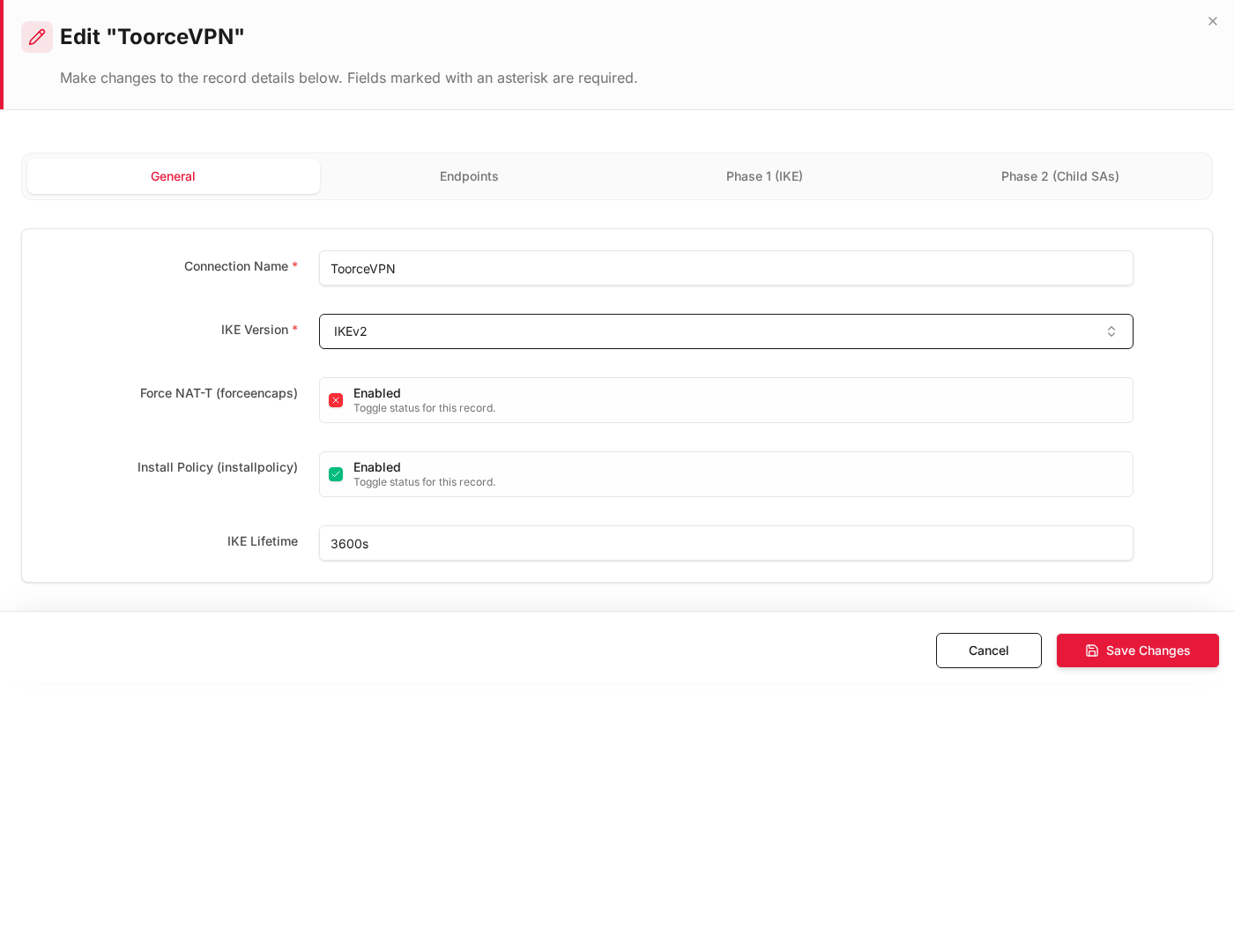
Install Policy auto-creates inline rules (for example to ipsec / in ipsec) when the tunnel is saved. You will edit the outbound rule to add X-Pool SNAT.
Endpoints tab
| Field | Value |
|---|---|
| Local Interface * | enp9s0 (WAN) |
| Local IP Address * | WAN IP or %any |
| Remote Peer IP / FQDN * | 203.0.113.10 |
Phase 1 (IKE) tab
| Field | Value |
|---|---|
| IKE Encryption | AES-256 |
| IKE Integrity | SHA256 |
| IKE DH Group | group14 |
| Pre-Shared Key | Strong shared secret |
Phase 2 (Child SAs) tab — identical local and remote subnets
Click + Add Row:
| Field | Value |
|---|---|
| ESP Encryption | AES-256 |
| ESP Integrity | SHA256 |
| PFS / DH Group | group14 |
| Local Networks | Local_LAN (192.168.1.0/24) |
| Remote Networks | Remote_LAN (192.168.1.0/24) |
| Enabled | Yes |
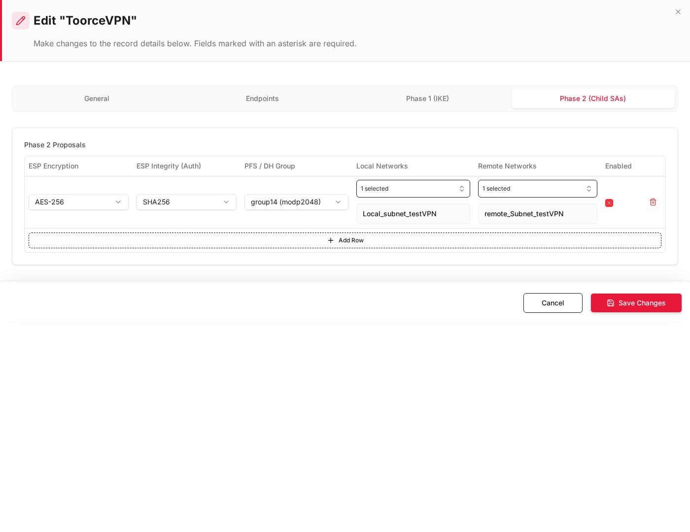
Both selectors show 192.168.1.0/24 — this is required when both sites share the same subnet.
- Click + Create Record.
- When the tunnel comes up, note the VPN interface name on the dashboard (for example
tun_ipsec_3 (Branch_Overlap_VPN)).
See IPSec VPN.
Step 3 — Phase 2 vs firewall policy alignment
When Install Policy is enabled, TOORCE creates firewall rules that must mirror Phase 2 selectors. Source uses the real local subnet; destination uses the Phase 2 remote network object.
| IPSec Phase 2 field | Inline rule field | Must match |
|---|---|---|
| Local Networks | Source Address Objects | Same CIDR — real local LAN (Local_LAN) |
| Remote Networks | Destination Address Objects | Same CIDR — Phase 2 remote (Remote_LAN) |
| (tunnel interface) | Destination Interface | VPN ifname, e.g. tun_ipsec_3 (ToorceVPN) |
| (LAN interface) | Source Interface | enp6s0 (LAN) |
Source = real local address: The rule source is the actual LAN subnet (
192.168.1.0/24), not the X-Pool. X-Pool translation happens in SNAT Policy on the NAT/SDWAN tab after the rule matches.
Step 4 — Edit outbound inline rule (LAN → VPN)
Go to Rules & Policies → Inline Rules. Edit the auto-created outbound rule (for example to ipsec) or create manually:
General
| Field | Value |
|---|---|
| Rule Name | LAN_to_VPN_XPool |
| Action | Allow |
| Status | Enabled |
Interfaces
| Field | Value |
|---|---|
| Source Interface * | enp6s0 (LAN) |
| Destination Interface * | tun_ipsec_3 (tun_ipsec_3(ToorceVPN)) — use your tunnel ifname |
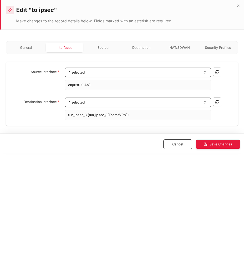
Destination Interface must be the VPN interface name (
tun_ipsec_*), not WAN.
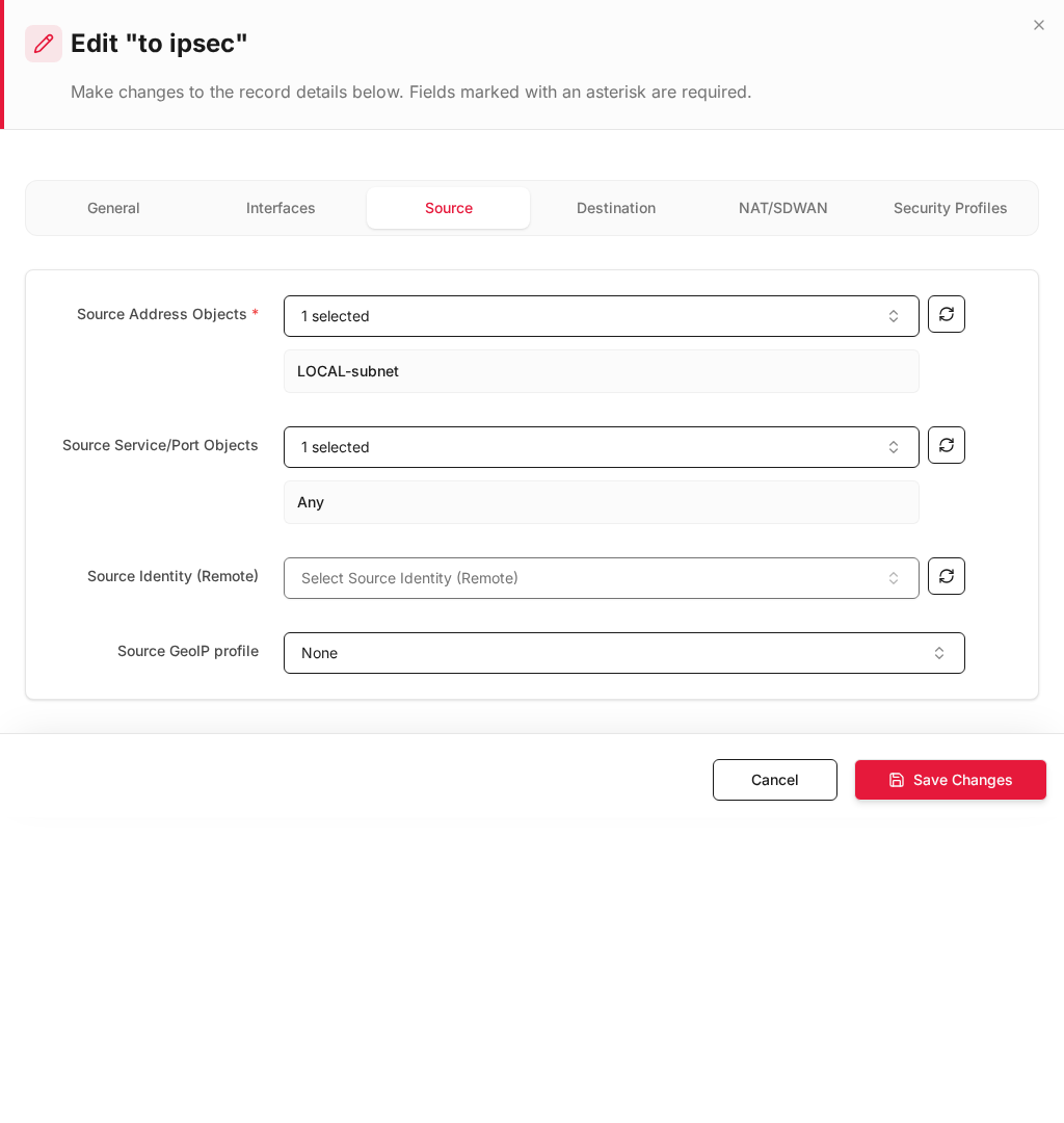
Source tab
| Field | Value |
|---|---|
| Source Address Objects * | Local_LAN — same object/CIDR as Phase 2 Local Networks |
| Source Service/Port Objects | Any |
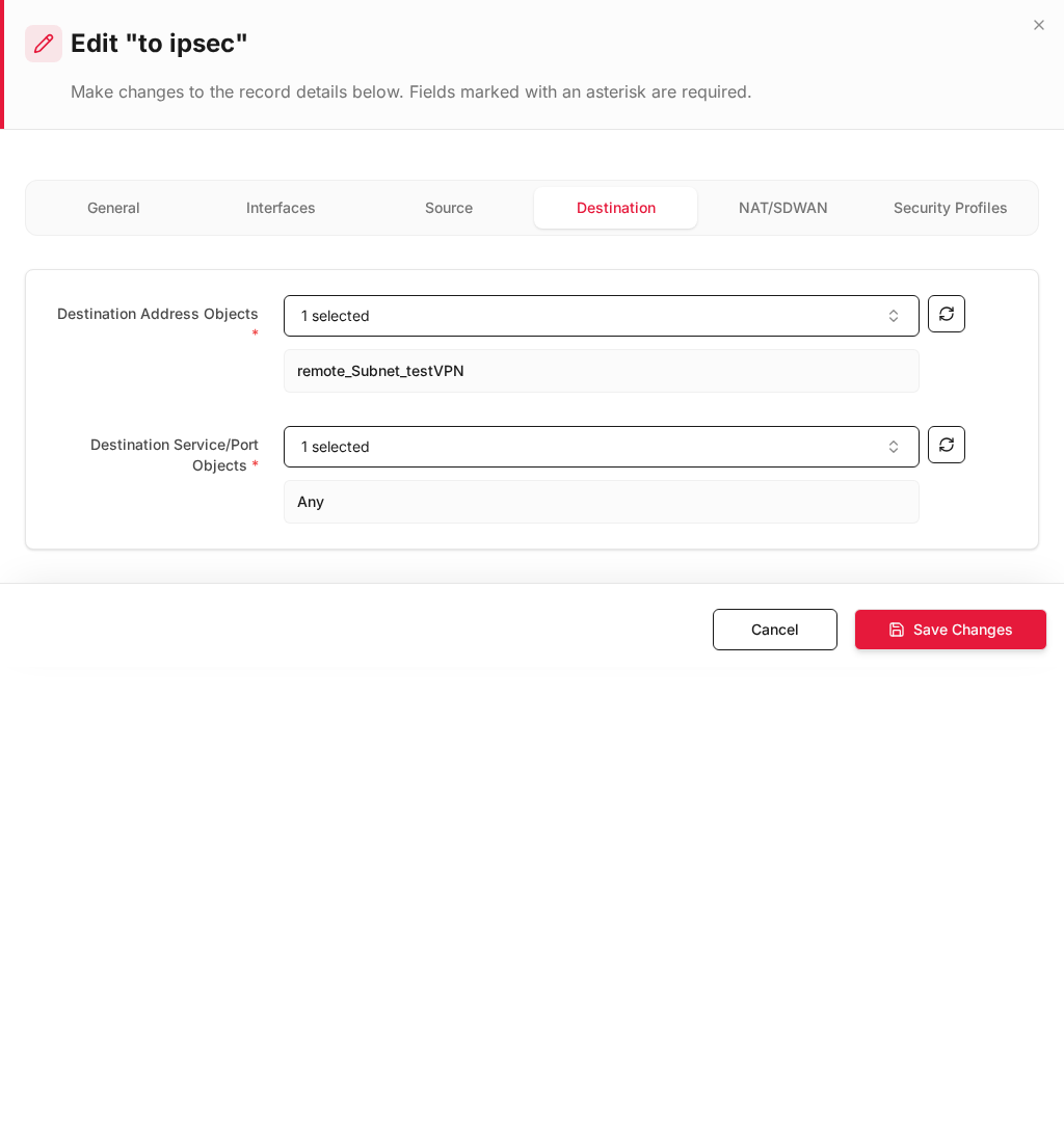
Destination tab
| Field | Value |
|---|---|
| Destination Address Objects * | Remote_LAN — same object/CIDR as Phase 2 Remote Networks |
| Destination Service/Port Objects * | Any |
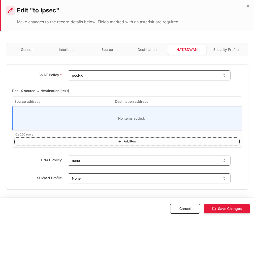
NAT/SDWAN tab — X-Pool SNAT
| Field | Value |
|---|---|
| SNAT Policy * | pool-X (X-Pool using 10.255.1.0/24) |
| DNAT Policy | none |
Available SNAT policies typically include:
| SNAT Policy | Use case |
|---|---|
Non /Route |
No NAT (default Install Policy rule) |
Auto using Same Interface Addr |
Internet SNAT |
pool-X |
X-Pool — translate local 192.168.1.x → 10.255.1.x |
- Click Save Changes.
For inbound traffic (remote → local) and DNAT with X-Pool, see X-Pool Overlapping NAT.
Step 5 — Install Policy (apply to running firewall)
- Click Install Policy in the top bar (same action after tunnel or rule changes).
- Confirm the tunnel is up and
tun_ipsec_*shows traffic on the dashboard.
| Check | Expected |
|---|---|
| IPSec tunnel status | Up / connected |
| VPN interface | tun_ipsec_3 (or your ID) visible under interfaces |
| Outbound rule | Source Local_LAN, Dest Remote_LAN, Dest IF = tun_ipsec_* |
| SNAT | pool-X active — remote sees 10.255.1.x |
| Phase 2 | Local and Remote both 192.168.1.0/24 |
Step 6 — Verify connectivity
| Test | From | To | Expected |
|---|---|---|---|
| LAN → remote host | 192.168.1.10 |
192.168.1.50 |
Ping/trace OK through tunnel |
| Remote sees SNAT source | Remote capture | — | Source IP 10.255.1.x, not 192.168.1.x |
| Wrong interface | Same traffic with Dest IF = WAN | — | Should fail (no SNAT/tunnel) |
| Firewall logs | Logs & Events → Firewall Security | — | Rule LAN_to_VPN_XPool / to ipsec |
Configuration checklist
| # | Item | Correct value |
|---|---|---|
| 1 | Install Policy on IPSec tunnel | Enabled |
| 2 | Phase 2 Local Networks | 192.168.1.0/24 |
| 3 | Phase 2 Remote Networks | 192.168.1.0/24 (identical to local) |
| 4 | Rule Source Address | Real local LAN — same CIDR as Phase 2 local |
| 5 | Rule Destination Address | Remote LAN — same CIDR as Phase 2 remote |
| 6 | Destination Interface | tun_ipsec_* VPN interface name |
| 7 | SNAT Policy | pool-X (X-Pool) |
| 8 | Install Policy (top bar) | Applied after all changes |
Troubleshooting
| Symptom | Check |
|---|---|
| Tunnel up, no traffic | Destination Interface = tun_ipsec_*? Phase 2 selectors match rule addresses? |
| Remote cannot reply | SNAT Policy = pool-X? Remote routes 10.255.1.0/24 via VPN? |
| Phase 2 mismatch | Local/Remote Networks in tunnel must equal rule Source/Destination CIDR |
| Install Policy rule wrong | Edit auto-created to ipsec rule — add X-Pool SNAT and verify interfaces |
| Duplicate subnet on LAN | Connected route on enp6s0 stays local; remote same-CIDR goes via VPN + SNAT |
Related documentation
- IPSec VPN
- X-Pool Overlapping NAT — DNAT for inbound / published services
- Inline Rules
- Address Objects
- Static Routes